In modern solar tracking systems, the solar panels are fixed on a structure that moves according to the position of the sun.
Let us design a solar tracker using two servo motors, a light sensor consisting of four LDRs and Arduino UNO board.


Let us design a solar tracker using two servo motors, a light sensor consisting of four LDRs and Arduino UNO board.
Circuit Diagram

The circuit design of solar tracker is simple but setting up the system must be done carefully.
Four LDRs and Four 100KΩ resistors are connected in a voltage divider fashion and the output is given to 4 Analog input pins of Arduino.
Recommended study
Working
LDRs are used as the main light sensors. Two servo motors are fixed to the structure that holds the solar panel. The program for Arduino is uploaded to the microcontroller. The working of the project is as follows.
LDRs sense the amount of sunlight falling on them. Four LDRs are divided into top, bottom, left and right.
For east – west tracking, the analog values from two top LDRs and two bottom LDRs are compared and if the top set of LDRs receive more light, the vertical servo will move in that direction.
If the bottom LDRs receive more light, the servo moves in that direction.
For angular deflection of the solar panel, the analog values from two left LDRs and two right LDRs are compared. If the left set of LDRs receive more light than the right set, the horizontal servo will move in that direction.
If the right set of LDRs receive more light, the servo moves in that direction.
Setup
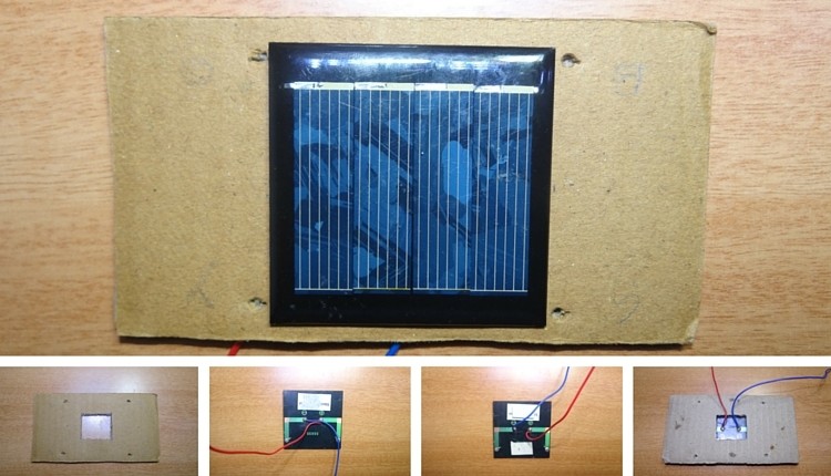
Step-1
- Take cardboard. Make a hole in the middle and four holes on four sides so that LDR fit into that.
- Stick the solar panel to the cardboard and bring two wires of the panel out as shown.
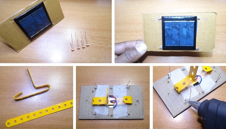
Step 2
- Now cut one of the two leads of the LDR so that one lead is shorter and other is longer.
- Insert these four LDRs into four holes as shown.
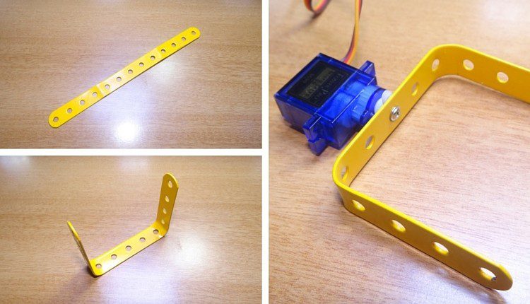
- Bend the straight Perforated metal strip as shown below.
- Place the bent metal strip on the back side of the cardboard
- Apply glue to the LDR to fix them firmly.
Step 3
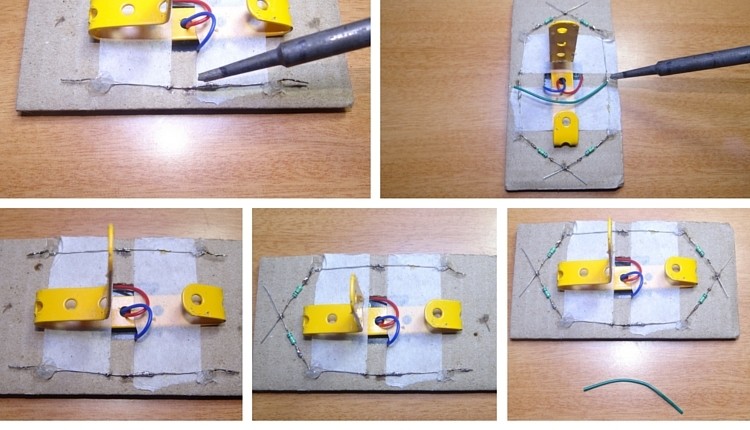
- Solder the two leads of LDR as shown
- To the other ends of LDR Solder resistors of 10k ohm
- Join the four leads of the 4 LDRs by connecting with a wire.
Step4
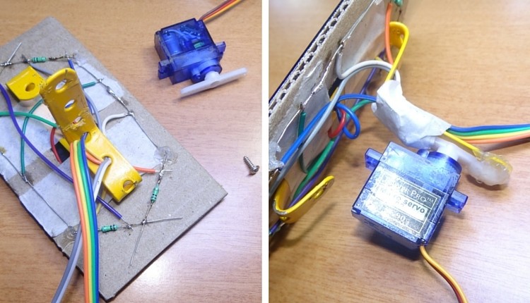
- Now take a bus wire.This is used to connect the Outputs of four LDRs to Arduino board.
- Insert it into metal strip as shown in the image.
- Now Solder the four wires to four LDRs at any point between LDR and resistor.
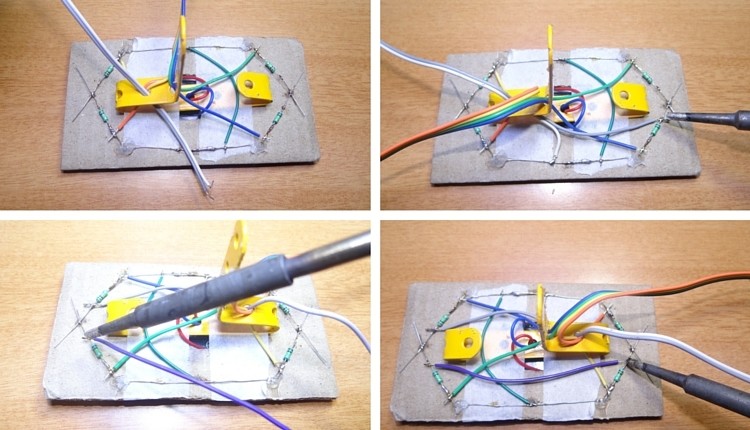
Step 5
- Insert another two wire bus into the perforated metal strip as shown.This is used for supplying Vcc and GND to LDR circuit.
- Solder one wire to the leads of LDRs which are connected to resistors and other wire to the other leads.
- Short the leads of LDRs connected to resistors using a wire as shown.
Step 6
- Now connect a servo motor to the Perforated metal strip using Screw.
- Apply glue to the servo to fix it firmly.
Step 7
- Take another straight Perforated metal strip and bend it as shown in the figure.
Step 8
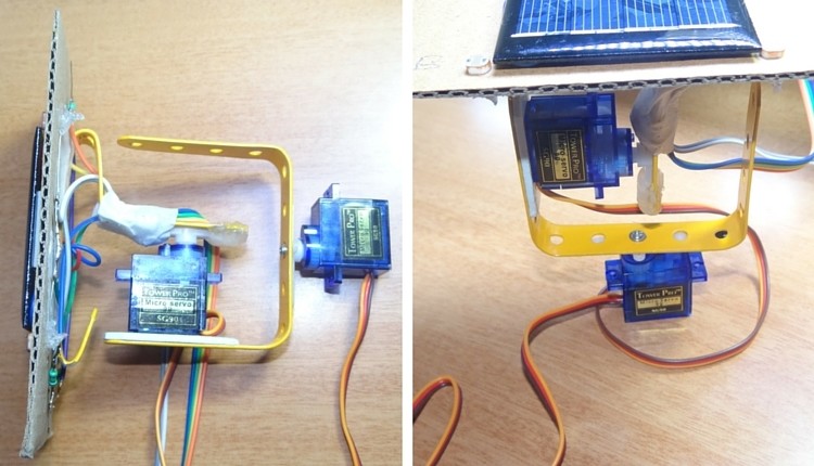
- Now place the set up of solar panel and first servo motor to the metal strip of second servo motor as shown.
Code:
#include <Servo.h>
//defining Servos
Servo servohori;
int servoh = 0;
int servohLimitHigh = 160;
int servohLimitLow = 20;
Servo servoverti;
int servov = 0;
int servovLimitHigh = 160;
int servovLimitLow = 20;
//Assigning LDRs
int ldrtopl = 2; //top left LDR green
int ldrtopr = 1; //top right LDR yellow
int ldrbotl = 3; // bottom left LDR blue
int ldrbotr = 0; // bottom right LDR orange
void setup ()
{
servohori.attach(10);
servohori.write(0);
servoverti.attach(9);
servoverti.write(0);
delay(500);
}
void loop()
{
servoh = servohori.read();
servov = servoverti.read();
//capturing analog values of each LDR
int topl = analogRead(ldrtopl);
int topr = analogRead(ldrtopr);
int botl = analogRead(ldrbotl);
int botr = analogRead(ldrbotr);
// calculating average
int avgtop = (topl + topr) / 2; //average of top LDRs
int avgbot = (botl + botr) / 2; //average of bottom LDRs
int avgleft = (topl + botl) / 2; //average of left LDRs
int avgright = (topr + botr) / 2; //average of right LDRs
if (avgtop < avgbot)
{
servoverti.write(servov +1);
if (servov > servovLimitHigh)
{
servov = servovLimitHigh;
}
delay(10);
}
else if (avgbot < avgtop)
{
servoverti.write(servov -1);
if (servov < servovLimitLow)
{
servov = servovLimitLow;
}
delay(10);
}
else
{
servoverti.write(servov);
}
if (avgleft > avgright)
{
servohori.write(servoh +1);
if (servoh > servohLimitHigh)
{
servoh = servohLimitHigh;
}
delay(10);
}
else if (avgright > avgleft)
{
servohori.write(servoh -1);
if (servoh < servohLimitLow)
{
servoh = servohLimitLow;
}
delay(10);
}
else
{
servohori.write(servoh);
}
delay(50);
}
Code:
#include <Servo.h> //defining Servos Servo servohori; int servoh = 0; int servohLimitHigh = 160; int servohLimitLow = 20; Servo servoverti; int servov = 0; int servovLimitHigh = 160; int servovLimitLow = 20; //Assigning LDRs int ldrtopl = 2; //top left LDR green int ldrtopr = 1; //top right LDR yellow int ldrbotl = 3; // bottom left LDR blue int ldrbotr = 0; // bottom right LDR orange void setup () { servohori.attach(10); servohori.write(0); servoverti.attach(9); servoverti.write(0); delay(500); } void loop() { servoh = servohori.read(); servov = servoverti.read(); //capturing analog values of each LDR int topl = analogRead(ldrtopl); int topr = analogRead(ldrtopr); int botl = analogRead(ldrbotl); int botr = analogRead(ldrbotr); // calculating average int avgtop = (topl + topr) / 2; //average of top LDRs int avgbot = (botl + botr) / 2; //average of bottom LDRs int avgleft = (topl + botl) / 2; //average of left LDRs int avgright = (topr + botr) / 2; //average of right LDRs if (avgtop < avgbot) { servoverti.write(servov +1); if (servov > servovLimitHigh) { servov = servovLimitHigh; } delay(10); } else if (avgbot < avgtop) { servoverti.write(servov -1); if (servov < servovLimitLow) { servov = servovLimitLow; } delay(10); } else { servoverti.write(servov); } if (avgleft > avgright) { servohori.write(servoh +1); if (servoh > servohLimitHigh) { servoh = servohLimitHigh; } delay(10); } else if (avgright > avgleft) { servohori.write(servoh -1); if (servoh < servohLimitLow) { servoh = servohLimitLow; } delay(10); } else { servohori.write(servoh); } delay(50); }
Nice post, thanks for sharing with us
ReplyDeleteSpy Shop Online is a leading platform offering the most economical solutions in the form of mobile jammers on rent for exam hall. Call us today for more details.