In this post I show how to set up the HC-05 to always connect to the same HC-06 (or HC-05 in Slave mode). For this we use PAIR, BIND, and LINK.
I am using 2 separate Arduino IDEs; version 1.6.3 which is installed, and version 1.0.5 which I run from a folder (it is the non-install version). This allows me to use 2 IDEs at the same time, each connected to a different Arduino. It also gives me 2 serial monitors, one for each Arduino.
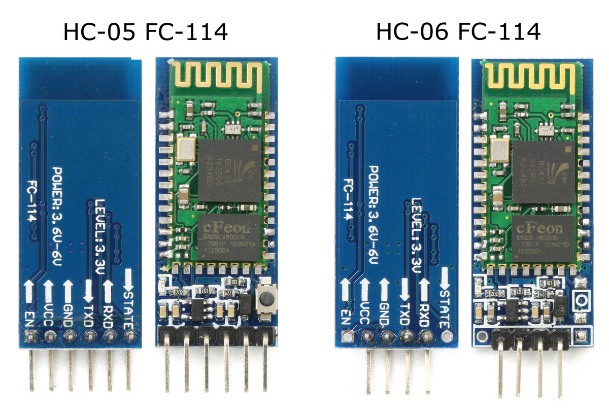
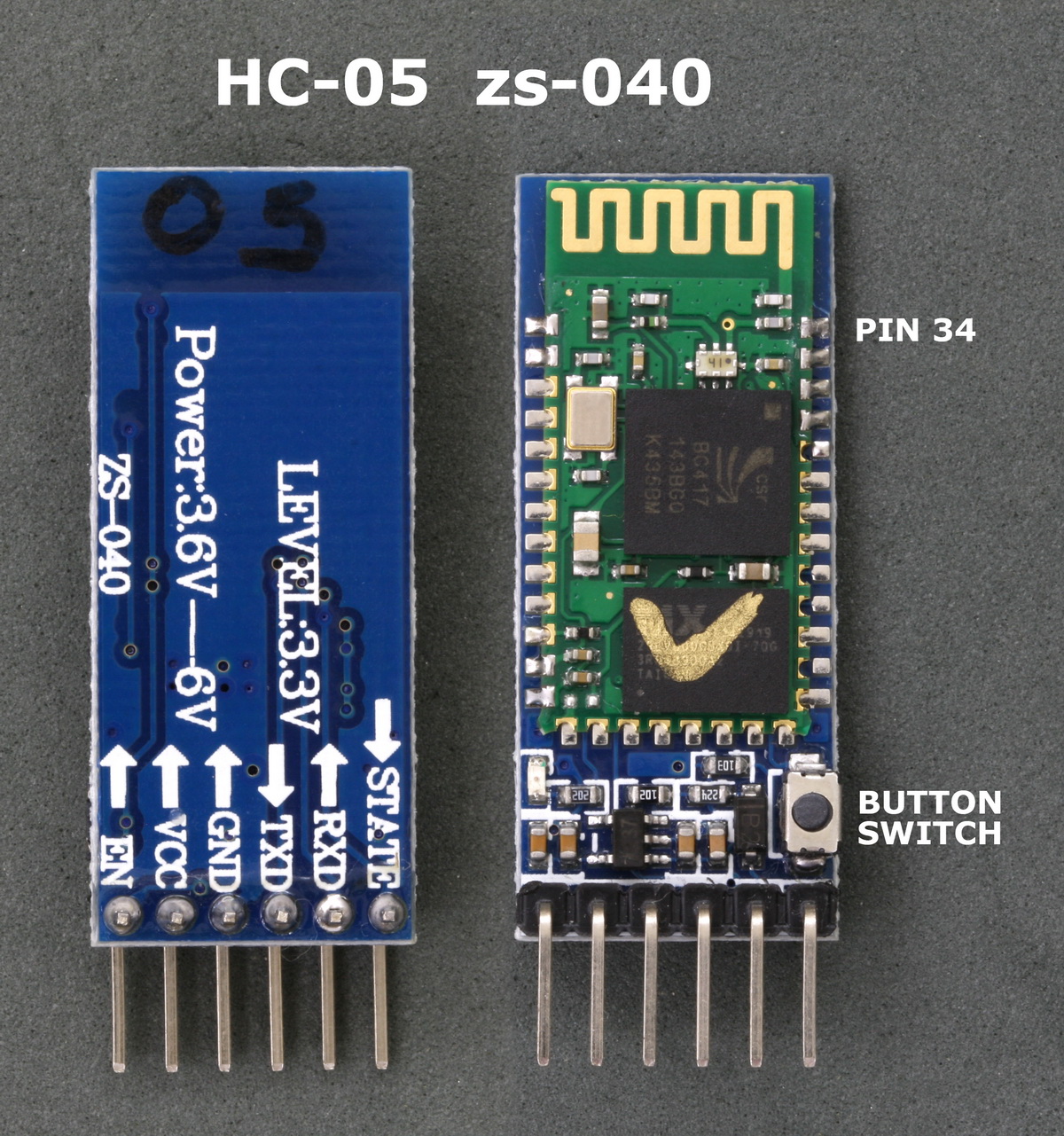
The modules used are the zs-040 versions of the HC-05 and the HC-06. The HC-05 has the Wavesen/HC firmware 2.0-20100601 and any module running the same firmware will be the same.
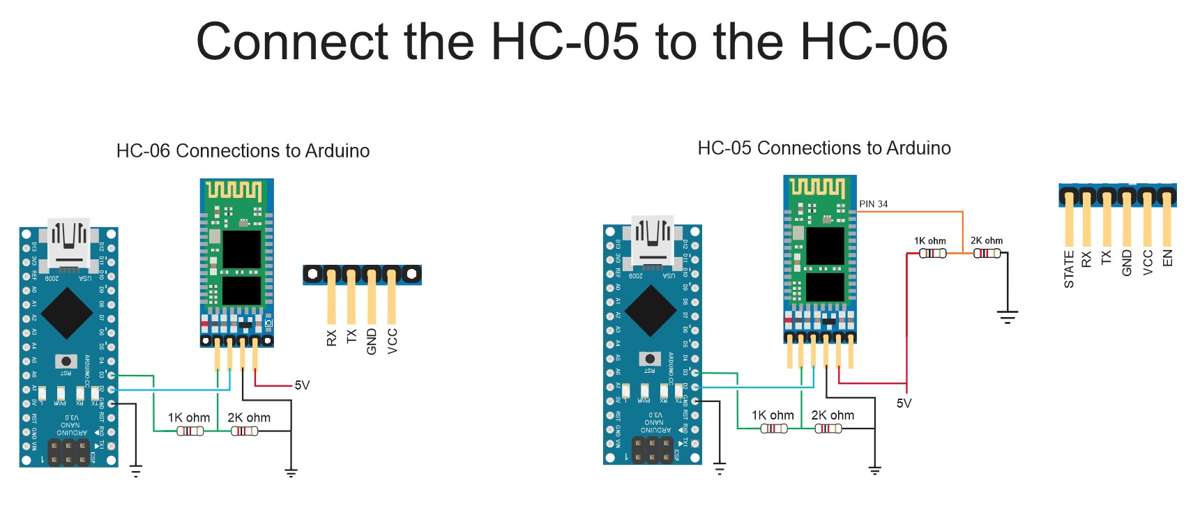
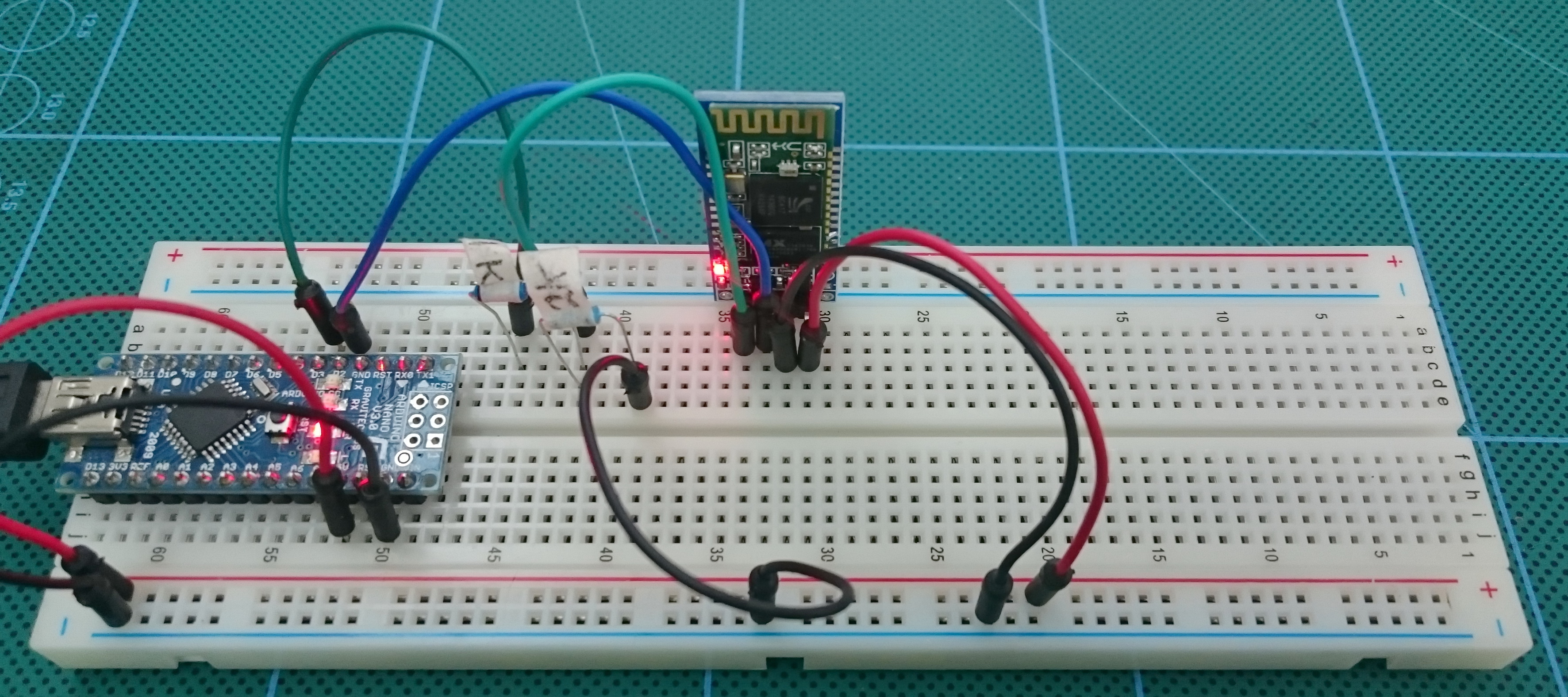
The HC-05 has 2 AT command modes which I refer to as “mini” AT mode and “full” AT mode and some commands only work when in “full” AT mode. To enter “full” AT mode pin 34 needs to be HIGH and kept HIGH. To accomplish this I have made a connection from pin 34 to +3.3v. See the diagram below (or after the jump).
Connections
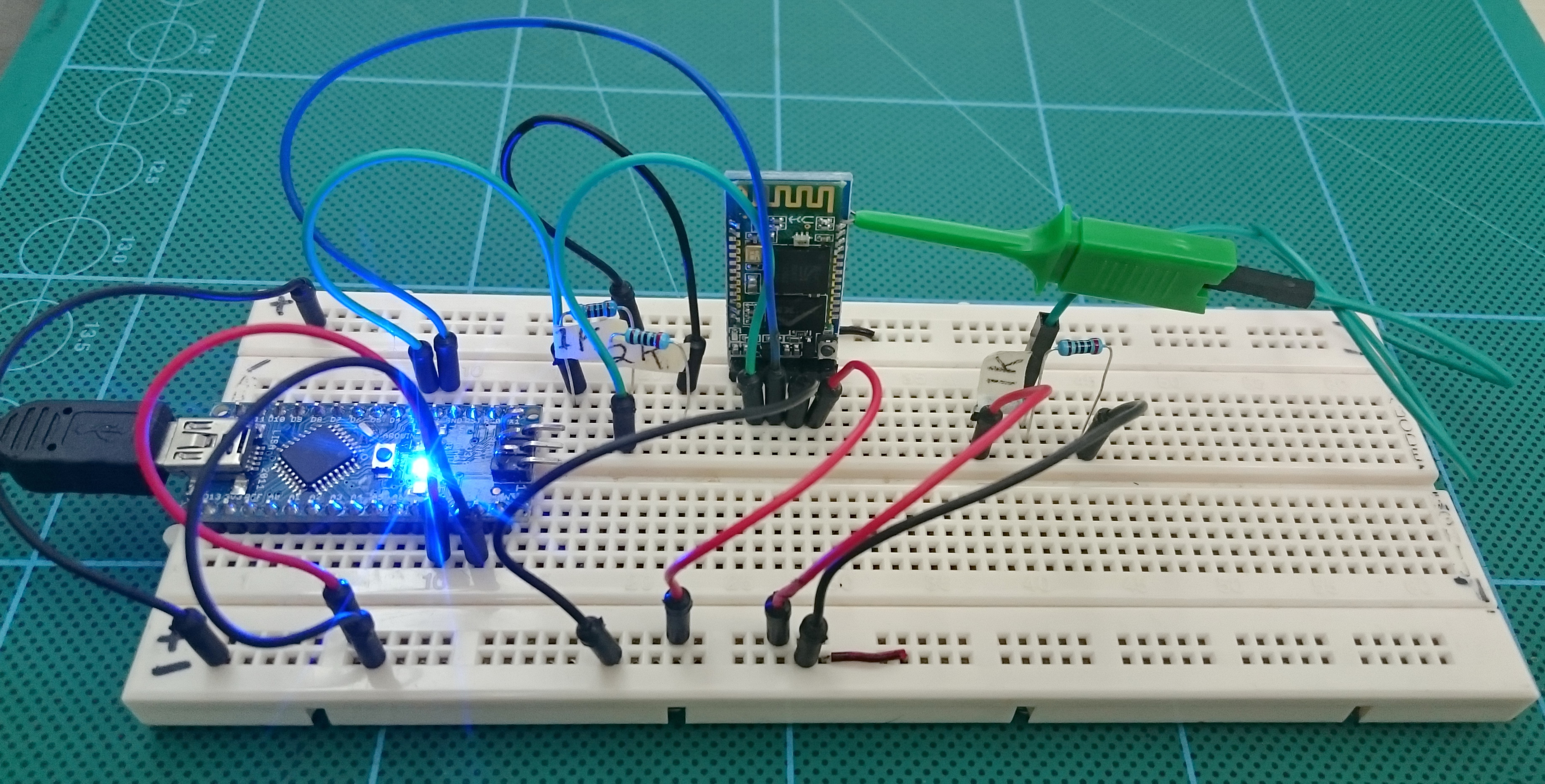
I have 2 Arduinos. One connected to a HC-05 zs-040 and one connected to a HC-06 zs-040.
The HC-05 has a connection from pin 34 to +3.3v. This activates “full” AT mode.

HC-05 Set Up
I have the HC-05 set with the following values:
– ROLE = 0 (slave mode)
– UART = 9600 (baud rate for communication mode)
– CMODE = 0 (only connect to paired devices)
– PSWD = 1234 (password/PIN for pairing)
– UART = 9600 (baud rate for communication mode)
– CMODE = 0 (only connect to paired devices)
– PSWD = 1234 (password/PIN for pairing)
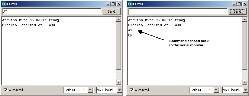
In AT mode I will be using a baud rate of 38400.
Build the circuit, power on and load the following sketch.
Because pin 34 on the Bluetooth module is brought HIGH, the HC-05 should enter AT mode on power on.
Open the serial monitor on the host computer and confirm you are in AT mode by typing “AT” (no quotes). You should get a reply of “OK”
Remember that the HC-05 requires “Both NL & CR” to be set.
Open the serial monitor on the host computer and confirm you are in AT mode by typing “AT” (no quotes). You should get a reply of “OK”
Remember that the HC-05 requires “Both NL & CR” to be set.
The sketch echos the commands you enter back to the serial monitor. This makes it a bit easier to follow.

HC-06 Set Up
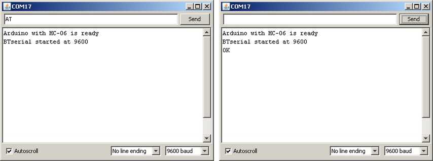
Build the HC-06 circuit, power on and load the following sketch. My HC-06 is set to use 9600 baud rate. If yours is using a different speed then you will need to change the sketch. Change the following lines:
BTSerial.begin(9600);
Serial.println(“BTserial started at 9600″);
Change the 9600 to what ever speed your HC-06 is using.
BTSerial.begin(9600);
Serial.println(“BTserial started at 9600″);
Change the 9600 to what ever speed your HC-06 is using.
HC-06 modules start in AT mode so we can start entering commands as soon as we open the serial monitor. Remember that the HC-06 requires commands to be upper case and does not want new lines or carriage returns so set “No line endings” at the bottom of the serial monitor window. Open the serial monitor on the host computer and confirm you are in AT mode by typing “AT” (no quotes). You should get a reply of “OK”
We don’t need to do much to prepare the HC-06. Just make sure the password is the same as the HC-05.
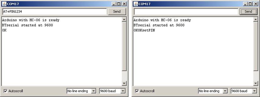
To change the password/PIN to 1234 enter “AT+PSWD1234″ (no quotes) and click Send
To change the password/PIN to 1234 enter “AT+PSWD1234″ (no quotes) and click Send
Pairing and Binding
At this point we should have the HC-06 waiting for a connection. The password/PIN is 1234.
The steps to connect to the HC-06 are
1. set the same baud rate on both devices.
2. make sure the passwords on the HC-05 and the HC-06 are the same
3. find the address of the HC-06
4. pair the HC-05 with the HC-06
5. bind the HC-06 to the HC-05
6. set the HC-05 to only connect with paired devices
7. link to the HC-06
1. set the same baud rate on both devices.
2. make sure the passwords on the HC-05 and the HC-06 are the same
3. find the address of the HC-06
4. pair the HC-05 with the HC-06
5. bind the HC-06 to the HC-05
6. set the HC-05 to only connect with paired devices
7. link to the HC-06
1. Set the same baud rate on both devices.
Set the communication mode baud rate to 9600 on the HC-05 and the HC-06. I have already done this.
This is only for the purpose of this example. Once you have got everything working you can change the baud rates.
This is only for the purpose of this example. Once you have got everything working you can change the baud rates.
2. Make sure the passwords on the HC-05 and the HC-06 are the same
We have already set the passwords.
3. Find the address of the HC-06
You can do this with an Android device or you can do it with the HC-05. Here is how to it with the HC-05.
Make sure the HC-05 is in AT mode and enter the following commands.
AT+RMAAD
AT+ROLE=1
AT+RESET

AT+RMAAD
AT+ROLE=1
AT+RESET
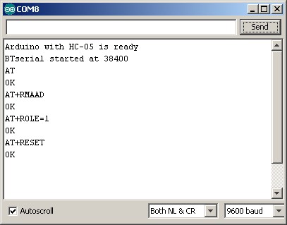
AT+RMAAD clears any previously paired devices.
AT+ROLE=1 puts the HC-05 in Master Mode
AT+RESET reset the HC-05. This is sometimes needed after changing roles.
AT+ROLE=1 puts the HC-05 in Master Mode
AT+RESET reset the HC-05. This is sometimes needed after changing roles.
Now enter the following
AT+CMODE=0
AT+INQM=0,5,9
AT+INIT
AT+INQ
AT+CMODE=0
AT+INQM=0,5,9
AT+INIT
AT+INQ
AT+INQM=0,5,9, AT+INIT and AT+INQ require pin 34 to be HIGH. If pin 34 is not HIGH then you will not receive any reply from these commands. No message, no error message.

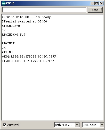
AT+CMODE=0 allows the HC-05 to connect to any device
AT+INQM=0,5,9 set inquiry to search for up to 5 devices for 9 seconds
AT+INIT initiates the SPP profile. If SPP is already active you will get an error(17) which you can ignore.
AT+INQ searches for other Bluetooth devices.
AT+INQM=0,5,9 set inquiry to search for up to 5 devices for 9 seconds
AT+INIT initiates the SPP profile. If SPP is already active you will get an error(17) which you can ignore.
AT+INQ searches for other Bluetooth devices.
In the above screen shot you can see that the HC-05 found 2 Bluetooth devices.
+INQ:A854:B2:3FB035,8043C,7FFF
+INQ:3014:10:171179,1F00,7FFF
One of these is the HC-06. To find out we can use the AT+RNAME? command.
+INQ:A854:B2:3FB035,8043C,7FFF
+INQ:3014:10:171179,1F00,7FFF
One of these is the HC-06. To find out we can use the AT+RNAME? command.
AT+INQ returns 3 values, the first is the address and this is the value we need. The second value is the class of the device and the third value is the signal strength (RSSI).
AT+INQ will only work if the HC-05 is in Master Mode and after a AT+INIT command.
AT+INQ will only work if the HC-05 is in Master Mode and after a AT+INIT command.
To get the name of the found devices we use the AT+RNAME? command. The address is the first field returned by AT+INQ; A854:B2:3FB035 and 3014:10:171179.
When we enter the address we need to replace the colons with commas. The format is AT+RNAME?A854,B2,3FB035 and AT+RNAME?3014,10,171179
Of course, you would use the address of your HC-06.

You can see from the above. A854:B2:3FB035 is my TV and 3014:10:171179 is the HC-06.
Of course, you would use the address of your HC-06.
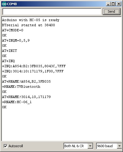
You can see from the above. A854:B2:3FB035 is my TV and 3014:10:171179 is the HC-06.
Now we have the address of the HC-06 we can finish making the connection.
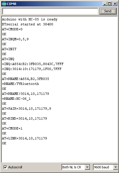
4. Pair the HC-05 with the HC-06
To pair we use the AT+PAIR=<addr>,<timeout> command.
Enter “AT+PAIR=3014,10,171179,9″ (no quotes)
If the HC-05 cannot pair with the HC-06 within 9 seconds you will get an error message. If the pairing is successful you will get an “OK”
Enter “AT+PAIR=3014,10,171179,9″ (no quotes)
If the HC-05 cannot pair with the HC-06 within 9 seconds you will get an error message. If the pairing is successful you will get an “OK”
5. Bind the HC-06 to the HC-05
Bind using “AT+BIND=3014,10,171179″
6. Set the HC-05 to only connect with paired devices
We do this with the CMODE command – “AT+CMODE=1″
7. Link to the HC-06
Use the link command AT+LINK=<addr>
In my case “AT+LINK=3014,10,171179″. If all is well you will get the “OK” reply.
In my case “AT+LINK=3014,10,171179″. If all is well you will get the “OK” reply.
The LED on the HC-05 should have 2 quick blinks every 2 seconds (or so).
The LED on the HC-06 should be on (not blinking).
You have now connected the HC-05 and the HC-06
The LED on the HC-06 should be on (not blinking).
You have now connected the HC-05 and the HC-06
Now that the connection has been formed, the HC-05 will automatically connect to the HC-06 every time they are turned on.
Once the connection is formed the HC-05 will switch to communication mode. If you want to continue with AT Mode then you will need to reset the module with pin 34 HIGH or with the button switch closed.
Test The Connection
On the HC-05, remove the connection to pin 34 and upload the following sketch to the Arduino connected to it. The sketch opens the BTserial at 9600 for communication mode.
Reset both Arduinos and remove power from the HC-05 and the HC-06
Power on the HC-06. The LED should be rapidly blinking 5 times per second. This indicates it is waiting for a connection or to be paired.
Power on the HC-05. The LED will blink a couple of times when first on and then change to a the regular pattern of blinking quickly every couple of seconds.
The LED on the HC-06 will turn on full time (no blinking).
The modules are now connected.
Power on the HC-05. The LED will blink a couple of times when first on and then change to a the regular pattern of blinking quickly every couple of seconds.
The LED on the HC-06 will turn on full time (no blinking).
The modules are now connected.
Open the serial monitors and what ever you enter in one will appear the the other and visa versa
Every time the modules are powered on they should connect. If you find they do not connect then cycle the power to the Arduinos. Sometimes the HC-05 will get stuck trying to make a connection. In this case the LED on the HC-05 will either
1. quickly blink 3 times every couple of seconds.
2. blink on/off twice a second.
This normally happens when the HC-06 is turned off and then back on again without resetting the HC-05.
1. quickly blink 3 times every couple of seconds.
2. blink on/off twice a second.
This normally happens when the HC-06 is turned off and then back on again without resetting the HC-05.
The devices seem to connect more quickly when the HC-06 is started first.
Comments
Post a Comment