
Previous Article: Four Seven Segment Display
This month’s Arduino project is to build two 2-digit 7-segment display circuits and sketches, one that counts up and one that counts up using mini push buttons. The next posts will explain the circuits and the Arduino sketches.
Components:
- Arduino Mega or Arduino UNO
- 1 2-digit 7-segment display (I got a 50-piece LED display grab bag for better value (plus the fun factor!) the one I used was configured as shown)
- 2 Mini push-button switches
- 9 Resistors 100 Ohm
- 2 Resistors 10K Ohm
- 2 2N3906 transistors (PNP)
- 1 Solderless breadboard
- Jumper wires in assorted lengths

Code:
// www.TinkerHobby.com
// Natalia Fargasch Norman
// Dual seven-segment LED Display
// Common Anode digit 1 pin 10
// Common Anode digit 2 pin 5

//       CA1 G  F  A  B
//        |  |  |  |  |      -> pins and segments they control
//   ---------    ---------
//   |   A   |    |   A   |
//  F|       |B  F|       |B
//   |---G---|    |---G---|
//  E|       |C  E|       |C
//   |   D   |    |   D   |
//   ---------    ---------
//        |  |  |  |  |      -> pins and segments they control
//        D  DP E  C CA2

// Segments that make each number when lit:
// 0 => -FEDCBA
// 1 => ----BC-
// 2 => G-ED-BA
// 3 => G--DCBA
// 4 => GF--CB-
// 5 => GF-DC-A
// 6 => GFEDC-A
// 7 => ----CBA
// 8 => GFEDCBA
// 9 => GF-DCBA

// Arduino digital pins used to light up
// corresponding segments on the LED display
#define A 3
#define B 2
#define C 6
#define D 8
#define E 7
#define F_SEG 4
#define G 5

// Pins driving common anodes
#define CA1 13
#define CA2 12

// Pins for A B C D E F G, in sequence
const int segs[7] = { A, B, C, D, E, F_SEG, G };

// Segments that make each number
const byte numbers[10] = { 0b1000000, 0b1111001, 0b0100100, 0b0110000, 0b0011001, 0b0010010,
0b0000010, 0b1111000, 0b0000000, 0b0010000 };

void setup() {
  pinMode(A, OUTPUT);
  pinMode(B, OUTPUT);
  pinMode(C, OUTPUT);
  pinMode(D, OUTPUT);
  pinMode(E, OUTPUT);
  pinMode(F_SEG, OUTPUT);
  pinMode(G, OUTPUT);
  pinMode(CA1, OUTPUT);
  pinMode(CA2, OUTPUT);
}

void loop() {
  for (int digit1=0; digit1 < 10; digit1++) {
    for (int digit2=0; digit2 < 10; digit2++) {
      unsigned long startTime = millis();
      for (unsigned long elapsed=0; elapsed < 600; elapsed = millis() - startTime) {
        lightDigit1(numbers[digit1]);
        delay(5);
        lightDigit2(numbers[digit2]);
        delay(5);
      }
    }
  }
}

void lightDigit1(byte number) {
  digitalWrite(CA1, LOW);
  digitalWrite(CA2, HIGH);
  lightSegments(number);
}

void lightDigit2(byte number) {
  digitalWrite(CA1, HIGH);
  digitalWrite(CA2, LOW);
  lightSegments(number);
}

void lightSegments(byte number) {
  for (int i = 0; i < 7; i++) {
    int bit = bitRead(number, i);
    digitalWrite(segs[i], bit);
  }
}
There are a few options to control multiple displays:
- employing multiple controllers;
- using a 7-segment driver chip like the 7447;
- using a multi-display controller such as the MAXIM MAX7219;
- sequencing through the displays, which is what we have done in our example, as it requires no added hardware.
When we were using a single-digit display, we connected the common anode pin to our Vdd supply, but with two digits we have to drive them independently if we want them to display different digits!
A natural reaction would be to try to use two Arduino I/O pins, each driving a digit of the display. The problem with this scenario is that it is not possible to drive the common anode or cathode pin using Arduino I/O pins, as they cannot source or sink enough current to light all seven segments.

2-digit 7-segment led display diagram
The solution is then to use bipolar junction transistors (NPN for common cathode and PNP for common anode displays) in order to sink or drive the required current. The controlling interface outputs the value for a specific display by enabling only its common pin transistor, and the digit driven by that common pin becomes active.
To give the impression that both displays are active at the same time and avoid flickering we cycle through the digits in quick succession and keep each of them lit for 5ms. We will see how that was implemented when we go over the sketch next week.
Here is the schematic for the 2-digit 7-segment display circuit (click for larger image):

So now on the the meatier sections of the sketch for this project:
Common anode displays are not immediately obvious as a segment is lit when the corresponding pin is made LOW. You might be surprised, though, that common anode displays are most often used because they can be used with 74xx series logic data-selector chips and general purpose general purpose PNP transistors.
// Segments that make each number when lit:
// 0 => -FEDCBA
// 1 => ----BC-
// 2 => G-ED-BA
// 3 => G--DCBA
// 4 => GF--CB-
// 5 => GF-DC-A
// 6 => GFEDC-A
// 7 => ----CBA
// 8 => GFEDCBA
// 9 => GF-DCBA
Remember, the Arduino pins are connected to the display’s cathodes. To light a segment we make the corresponding pin LOW.
We use 0s where the segments need to be lit up. The digit ‘zero’, for instance, is not the intuitive 0b0111111, but the less obvious 0b1000000.
// Segments that make each number
const byte numbers[10] = { 0b1000000, 0b1111001, 0b0100100, 0b0110000, 0b0011001, 0b0010010,
0b0000010, 0b1111000, 0b0000000, 0b0010000 };
To give the impression that both displays are active at the same time and avoid flickering we cycle through the digits in quick succession and keep each of them lit for 5ms. This is implemented by adding a short delay after displaying each digit. Since numbers stay lit for 600 ms, the whole process is repeated 60 times for each number displayed, and thanks to Persistence of Vision (POV) we have the impressios that both digits are actually lit up at the same time. (Even though they are not).
Arduino 2 digit 7 segment display counter sketch walk-through
The loop below is where the action takes place in our sketch: we cycle through both digits keeping each on for 5ms at a time for the 600ms during which we display each complete number.
void loop() {
  for (int digit1=0; digit1 < 10; digit1++) {
    for (int digit2=0; digit2 < 10; digit2++) {
      unsigned long startTime = millis();
      for (unsigned long elapsed=0; elapsed < 600; elapsed = millis() - startTime) {
        lightDigit1(numbers[digit1]);
        delay(5);
        lightDigit2(numbers[digit2]);
        delay(5);
      }
    }
  }
}
The lightDigit function for digit 1 enables only the transistor for the common anode pin of the tens digit:
void lightDigit1(byte number) {
  digitalWrite(CA1, LOW);
  digitalWrite(CA2, HIGH);
  lightSegments(number);
}
The lightDigit function for digit 2 enables only the transistor for the common anode pin of the units digit:
void lightDigit2(byte number) {
  digitalWrite(CA1, HIGH);
  digitalWrite(CA2, LOW);
  lightSegments(number);
}
Function lightSegments was reused from the single-digit 7-segment sketch:
void lightSegments(byte number) {
  for (int i = 0; i < 7; i++) {
    int bit = bitRead(number, i);
    digitalWrite(segs[i], bit);
  }
}
Next week we will modify our project to use buttons to control each digit, and as such we’ll avoid having to cycle through several numbers in order to achieve the desired number being displayed (if that number is significantly greater than the current number being displayed).
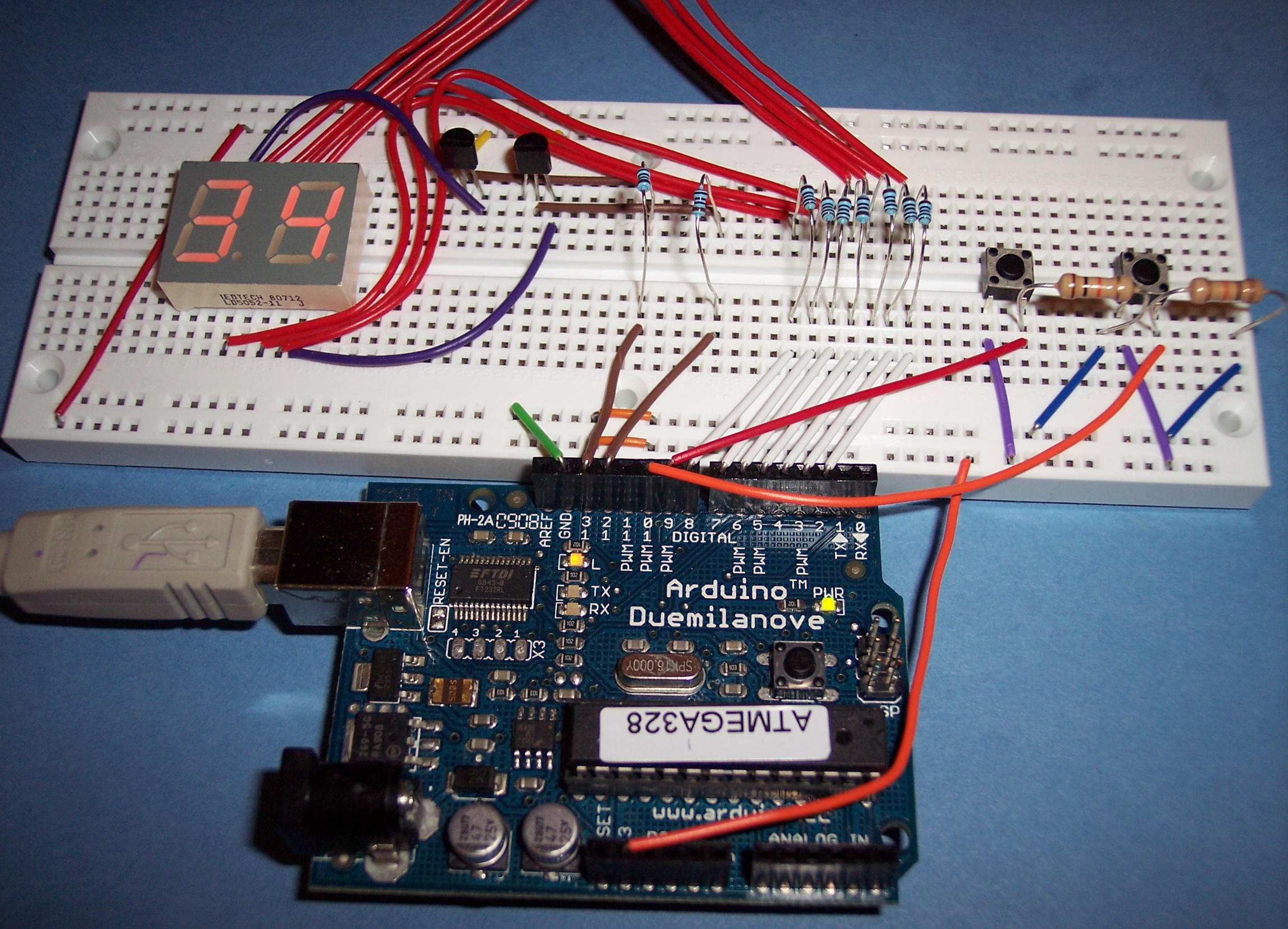
This week we modify the original circuit and sketch to include two buttons, one to control each digit of the display.
Here’s what the setup of our 2 digit 7 segment display with buttons looks like:
And here’s the complete sketch:
// www.TinkerHobby.com
// Natalia Fargasch Norman
// Dual seven-segment LED Display with buttons
// Common Anode digit 1 pin 10
// Common Anode digit 2 pin 5

//       CA1 G  F  A  B
//        |  |  |  |  |      -> pins and segments they control
//   ---------    ---------
//   |   A   |    |   A   |
//  F|       |B  F|       |B
//   |---G---|    |---G---|
//  E|       |C  E|       |C
//   |   D   |    |   D   |
//   ---------    ---------
//        |  |  |  |  |      -> pins and segments they control
//        D  DP E  C CA2

// Segments that make each number when lit:
// 0 => -FEDCBA
// 1 => ----BC-
// 2 => G-ED-BA
// 3 => G--DCBA
// 4 => GF--CB-
// 5 => GF-DC-A
// 6 => GFEDC-A
// 7 => ----CBA
// 8 => GFEDCBA
// 9 => GF-DCBA

// Arduino digital pins used to light up
// corresponding segments on the LED display
#define A 3
#define B 2
#define C 6
#define D 8
#define E 7
#define F_SEG 4
#define G 5

// Pushbuttons connected to pins 9 and 10
#define BTN1 9
#define BTN2 10

// Pins driving common anodes
#define CA1 13
#define CA2 12

// Pins for A B C D E F G, in sequence
const int segs[7] = { A, B, C, D, E, F_SEG, G };

// Segments that make each number
const byte numbers[10] = { 0b1000000, 0b1111001, 0b0100100, 0b0110000, 0b0011001, 0b0010010,
0b0000010, 0b1111000, 0b0000000, 0b0010000 };

int digit1 = 0;
int digit2 = 0;

void setup() {
  pinMode(A, OUTPUT);
  pinMode(B, OUTPUT);
  pinMode(C, OUTPUT);
  pinMode(D, OUTPUT);
  pinMode(E, OUTPUT);
  pinMode(F_SEG, OUTPUT);
  pinMode(G, OUTPUT);
  pinMode(BTN1, INPUT);
  pinMode(BTN2, INPUT);
  pinMode(CA1, OUTPUT);
  pinMode(CA2, OUTPUT);
}

void loop() {

  // check button1
  int val1 = digitalRead(BTN1);
  if (val1 == HIGH) {
    digit1++;
    digit1 %= 10;
    delay(10);
  }

  // check button2
  int val2 = digitalRead(BTN2);
  if (val2 == HIGH) {
    digit2++;
    digit2 %= 10;
    delay(10);
  }

  // display number
  unsigned long startTime = millis();
  for (unsigned long elapsed=0; elapsed < 600; elapsed = millis() - startTime) {
    lightDigit1(numbers[digit1]);
    delay(5);
    lightDigit2(numbers[digit2]);
    delay(5);
  }
}

void lightDigit1(byte number) {
  digitalWrite(CA1, LOW);
  digitalWrite(CA2, HIGH);
  lightSegments(number);
}

void lightDigit2(byte number) {
  digitalWrite(CA1, HIGH);
  digitalWrite(CA2, LOW);
  lightSegments(number);
}

void lightSegments(byte number) {
  for (int i = 0; i < 7; i++) {
    int bit = bitRead(number, i);
    digitalWrite(segs[i], bit);
  }
}
As you could see from last week’s full Arduino sketch listing, the source code for the 2-digit 7-segment display project using buttons is strikingly similar to the one without the buttons; praise for ‘copy and paste‘! (It is worth noting, though, that ‘copy and paste‘ can be responsible for a higher percentage of bugs than I’d care to admit).
There are just a couple of snippets that I would like to comment on:
2 Digit 7 Segment Display Sketch
The first part of the loop() function checks whether either button has been pressed and increments the value of each digit.
  // check button1
  int val1 = digitalRead(BTN1);
  if (val1 == HIGH) {
    digit1++;
    digit1 %= 10;
    delay(10);
  }

  // check button2
  int val2 = digitalRead(BTN2);
  if (val2 == HIGH) {
    digit2++;
    digit2 %= 10;
    delay(10);
  }
The line
digit1 %= 10;
which is shorthand for
digit1 = digit1 % 10;
accomplishes the same as the line
if (count == 10) count = 0;
that was used on the sketch for the single-digit 7-segment project a couple of months ago. It updates digit1 with the remainder of the division of itself by 10, which will be zero when digit1 is 10. The latter code looks a bit more obvious for beginner programmers.
The last part of the loop() function refreshes the display, and is very similar to the sketch for the 2-digit 7-segment display counter.
  // display number
  unsigned long startTime = millis();
  for (unsigned long elapsed=0; elapsed < 600; elapsed = millis() - startTime) {
    lightDigit1(numbers[digit1]);
    delay(5);
    lightDigit2(numbers[digit2]);
    delay(5);
  }
Are you looking for the best Sweets and Bakery Display Counter in cheapest price? We are providing Display Counter for food, Sweets and Bakery.
ReplyDeleteFor more information visit here : Display Counter