 In this project, we have designed a Simple Fan Regulator Circuit, which can be used to regulate the speed of a fan. This simple fan regulator circuit is implemented using very simple components.
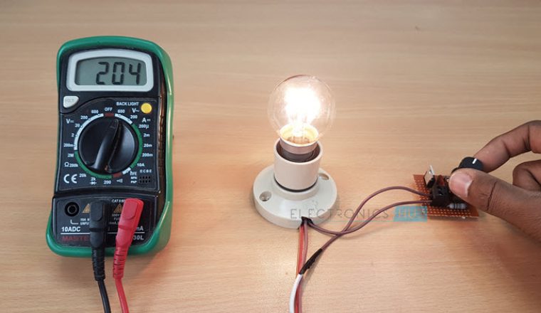
Obviously the power consumption by the fan will be less at lower speeds by this arrangement, but this is not an energy saving method. The voltage drop across the resistance is converted into heat losses (I2R), so the energy is dissipated in the form of heat.
This wastage of energy is more at high resistance or lower speed condition. Therefore, conventional fan voltage regulators have more energy losses.

Simple Electronic Voltage Regulator
Due to the advancement in power electronic technology, the alternative design of fan regulator (voltage regulator) can be easily implemented to reduce the energy losses that are caused by conventional voltage regulators.
 This type of voltage regulator is an energy saving device which uses TRIAC, DIAC and potentiometric resistance. This method provides the step less control of the fan speed by deriving the required amount of power from the main supply at a given instant.
Hence, the power is conserved rather than wasted unnecessarily. Let us discuss briefly about this voltage regulator circuit and its working.
 Now we are going to build a simple fan regulator circuit, which is generally used to control the speed of the fan in our homes or offices. As we know that by varying the firing angle of the TRIAC, the power applied through the load is controlled which is nothing but a concept of power control using TRIAC.
The same principle is applied to the voltage regulator circuit which we are going to discuss.
Required Components for Voltage Regulator Circuit
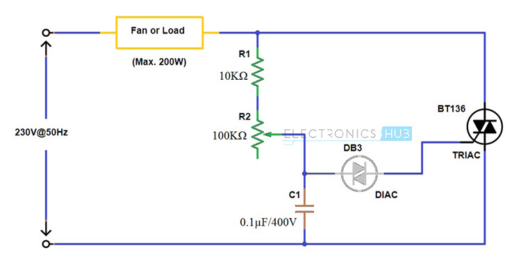
- Resistor R1 – 10 KΩ
- Variable resistance or potentiometer R2 – 100 KΩ
- Polyester capacitor C1 – 0.1 µ F (For operating range of up to 400 V)
- DIAC, D1 – DB3
- TRIAC, T1 – BT136
- A single phase ceiling fan or AC motor – 220 V, 50 Hz (range below 200 Watts)
Voltage Regulator Circuit Connection
- Recognize the terminals of all the components for positive and negative terminal connections. Choose the ceiling fan or any AC motor provided it should be rated below 200 watts (According to the values of the components selected)
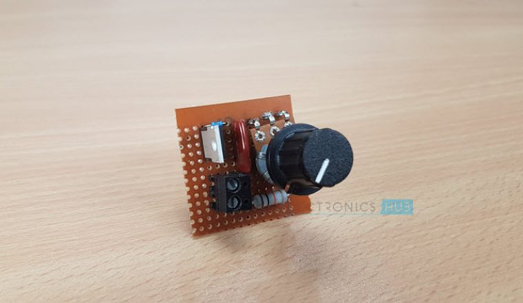
- Take a zero board or printed circuit board (PCB) and connect the circuit as given in the below diagram.
- The firing circuit consists of resistor R1, potentiometer R2, capacitor C1 and a DIAC. Connect the one terminal of the DIAC to the voltage divider combination of resistors and capacitor as shown in figure.
- Consider the data sheet of TRIAC BT 136 for recognizing the terminals of TRIAC and to know the other detailed information. Connect MT1 terminal to the neutral while MT2 to one end of the AC motor or load. And connect the gate terminal to the other end of DIAC.
- Connect the load or ceiling fan between the Phase or Line terminal of the AC power supply and MT2 terminal of TRIAC.
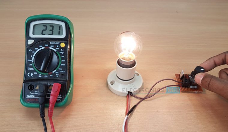
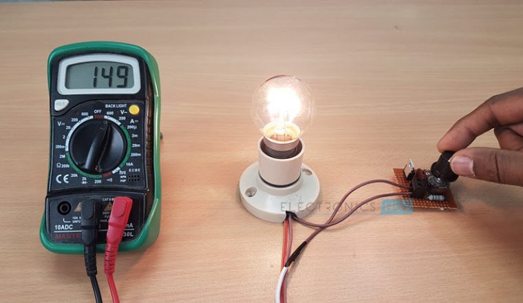
NOTE: For demonstration purpose, we have connected a light bulb to the simple fan regulator circuit along with a multimeter to show the voltage.
Circuit Diagram of Voltage Regulator using TRIAC, DIAC
Operation of the Electronic Voltage Regulator Circuit
- Before giving the power supply to this simple fan regulator circuit, keep the variable resistor or potentiometer in maximum resistance position so that no triggering is applied to TRIAC and hence the TRIAC will be in cutoff mode.
- Turn ON the power supply of the circuit and observe whether the fan is in standstill condition or not. Vary the potentiometer position slowly so that the capacitor starts charging at the time constant determined by the values of R1 and R2.
- Once the voltage across the capacitor is more than the break over voltage of the DIAC, DIAC starts conducting. Thus, the capacitor starts discharging towards the gate terminal of TRIAC through DIAC.
- Therefore, TRIAC starts conducting and hence the main current starts flowing into the fan through the closed path formed by TRIAC.
- By varying the potentiometer R2, the rate at which capacitor is going to be charged get varied this means that if the resistance is less, the capacitor will charge at a faster rate so the earlier will be the conduction of TRIAC.
- As the potentiometer resistance gradually increases, the conduction angle of TRIAC will be reduced. Hence the average power across the load will be varied.
- Due to the bidirectional control capability of both TRIAC and DIAC, it is possible to control the firing angle of the TRIAC in both positive and negative peaks of the input.
Note
- As a safety measure, test the good working condition of this circuit by applying a low voltage supply like 24V AC or 12 V AC with a small load like a low wattage bulb before connecting to the mains supply.
- If the load exceeds 200 watts, choose the higher watt capacity TRIAC in place BT 136 TRIAC.
Advantages of Simple Fan Regulator Circuit
- Continuous and step less control of the fan speed is possible
- Power saving is achieved at all the speeds by minimizing the energy losses
- Simple circuit which requires less number of components
- Efficient as compared with resistive type due to lower power consumption
- Cost-effective

Comments
Post a Comment