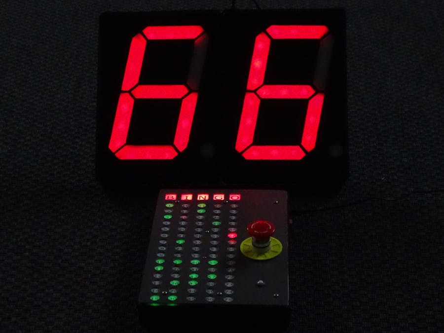
This Bingo Machine uses two-digit, A4-sized 7-segment displays with WS2811 LEDs and a scoreboard with WS2822 LEDs, all on one Arduino pin.


Story
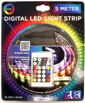
When walking in an ACTION store, I discovered a digital LED trip at an acceptable price (including 12V power adaptor and even including a controller with IR remote control). I decided to buy one and started to play with them with the aim to control the LED strip with an Arduino Uno in my case.
The complete package from ACTION
Although nowhere specified on the package or on the LED strip itself, soon I found out that this was as a type of strip with segments of three 5050 LEDs with one WS2811 driver per 3 LEDs.
Three LEDs and one driver and the data flow direction clearly visible
I connected the strip to an Arduino Uno to experiment with it using the Adafruit NeoPixel library and some example code such as RGBW strandtest.
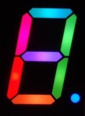
I started to do some brainstorming and came to the idea of using these trips for making an A4-size 7-segment display. Seven sections of strip as shown above would do the job plus one extra for the Decimal Point on the display. This is making it effectively 8 segments that would be controlled from just one output Pin of the Arduino and powered with the 12 V adaptor already contained in the ACTION package.
But what can you do with just one 7-segment Display?
I decided to make 2 of them and use them for creating a Bingo Machinedisplaying random numbers between 1 and 75 after the push of a button.
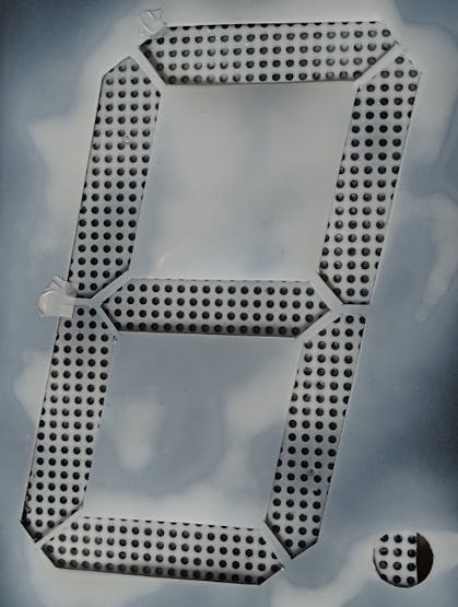
Step 1: Making the 7-Segment Displays
The finally produced digital large A4-sized 7-segment displays
The whole making process of the displays, is a pretty long story, which I could describe in a separate Tutorial. The short version of the making is as follows:
Both A4-size displays were made with conventional means and materials. When using laser cutters and 3D printers the whole process would be different and perhaps simpler. You find pretty good examples on the internet, e.g. YouTube (https://learn.adafruit.com/ninja-timer-giant-7-segment-display/overview) and you can even buy them ready made.
I found it a challenge and fun to make them myself..
For the LED strips I used 16 sections of 3 LEDS each cut from the WS2811 LED strip from ACTION.
2 * 8 segments of LED strip
These segments are connected by soldering wires to the +12V, GND and Do and Di of the strips. you can find lots of tutorials on the internet on how to do this properly.
For the housing I used a readily available and affordable Peg Board from the local ACTION store.
The Peg Board from ACTION modified and used for the housing of the 7-segment display
Remove the built-in LED strips used for backlighting the peg board
I used the cut out frontcovers of the peg board as a basis for mounting the LED segments
The new fronts of the housing were made of white translucent cutting board material from IKEA.
Template used to mark the positions of the LED sections on the re-used Peg-Board
A template was used to cut the segments out of a painted layer on top of the boards (black primer).
after painting remove the selfadhesive plastic template strips
A cheap audio cable (also from ACTION) was used to connect the 7_segment displays with just 3 wires (12V, GND and Data in) to the Arduino via a 220Ohm resistor.
Cheap audio cable to connect the 7-segment displays to the Arduino
I modified the housing to enable easy plugging-in of the audio connector.
cut the audio cable in two pieces; one part inside and the other part to connect to the ARDUINO
Step 2: Making the Scoreboard
I also decided to create a scoreboard display that would show the generated random numbers, a push button for generating a new number and a "bingo button" for ending and initiating a new round.
The finished scoreboard
The scoreboard is made using the same ACTION peg board as a housing (described above). The cover plate is made from a dark grey cutting board (again from ACTION) with holes drilled as can be seen above. The top cover is made from an IKEA cutting board. In between the 2 layers is a print on photo paper and a protective transparant foil.
Inside, taped against the back of the cutting board are 5 sections of 15 WS2812 LEDs each plus 3 * 8 LED strip sections for backlighting the word "BINGO."
The complete assembly of the scoreboard (including the Arduino board and 5V regulator)
Step 3: Making the Software
The initial experiments with the coding and playing with the LED strip and 7-Segment displays were done using an Arduino and a solderless breadboard.
Breadboard set up with 7-segment displays and WS2812 Led trip connected in paralel
A large momentary push button is connected to GND and to digital IO pin 2 of the Uno. Pushing the button starts the generation of a new random number. After a short "Light Show 1" the random number is shown on the two 7-segment displays.
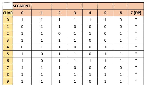
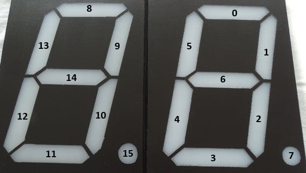
The table used for creating numbers on the 7-segment displays is as follows:
Conversion from Led strip number to segment on the Display
Numbering of the LED segments
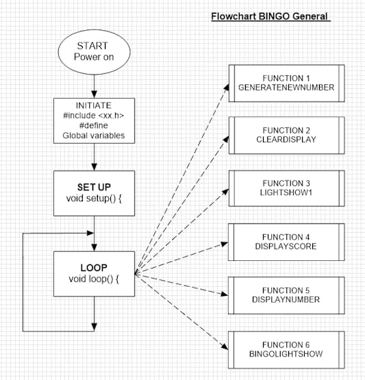
In order to help structuring the Arduino Sketch, I made some simple flow charts with the aid of ClickCharts a free version for non-commercial use (works fine once you get used to some inherent limitations)
General setup of the Bingo Programme (using free copy of ClickCharts ©
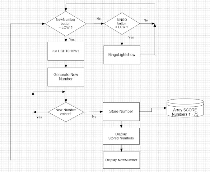
The LOOP flow chart
The generated number is stored in an array called SCORE[] consisting of 75 positions either filled with "0" or "1." If the generated new number already exists, automatically a new random number is generated.
The new number is lit on the scoreboard (with 75 numbers) and at the same time the new number is shown on the 7-Segment displays
The scoreboard keeps showing all the random numbers generated until a valid Bingo is achieved. A push button called "BINGO" will end the round with a short "BingoLightShow"
Hereafter the SCORE array is cleared and a new round can be started.
A New Round can also be started by toggling the power switch (disconnecting the 12V power) which will RESET the Arduino and restart the programme.
Step 4: The Electronics
A 12V, 2A charger supplies the power to the complete Bingo Machine.
The 12V input on the Arduino power jack has been modified to enable power switching (on - off).
The 5 V power for the 99 LEDs (75 + 24) used for the scoreboard is derived from the 12V input power by means of a 7805 voltage regulator (which can nearly handle the current drawn by the WS2812 LED strip); installing a Heatsink or a power version is recommended (in an update I will probably add a power transistor to deal with the required 5V power mainly consumed by the 99 WS2812 LEDs inside the scoreboard. I have made the sketch for the Arduino in such a way that the power demand of the scoreboard is moderate.
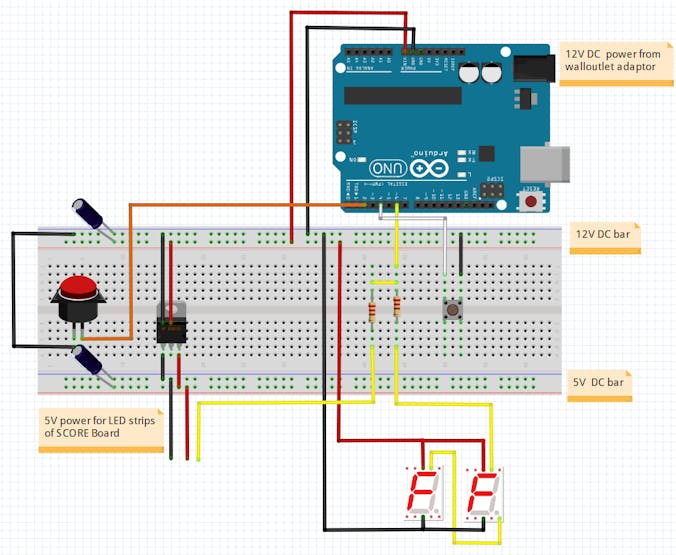
The layout in a Fritzing diagram looks as follows:
Fritzing diagram of the breadboard set up
Note that both the 7-segment LED sections (12V) as well as the LED strips illuminating the numbers 1 -75 on the Bingo scoreboard are controlled by one and the same output pin (6) from the Uno.
Bingo Machine A4-Size 7-Segment Displays With Arduino >>>>> Download Now
ReplyDelete>>>>> Download Full
Bingo Machine A4-Size 7-Segment Displays With Arduino >>>>> Download LINK
>>>>> Download Now
Bingo Machine A4-Size 7-Segment Displays With Arduino >>>>> Download Full
>>>>> Download LINK 1D